Ford Parts Wiki | GM Parts Wiki
Home | Search | Browse
Prev
 Next
Next
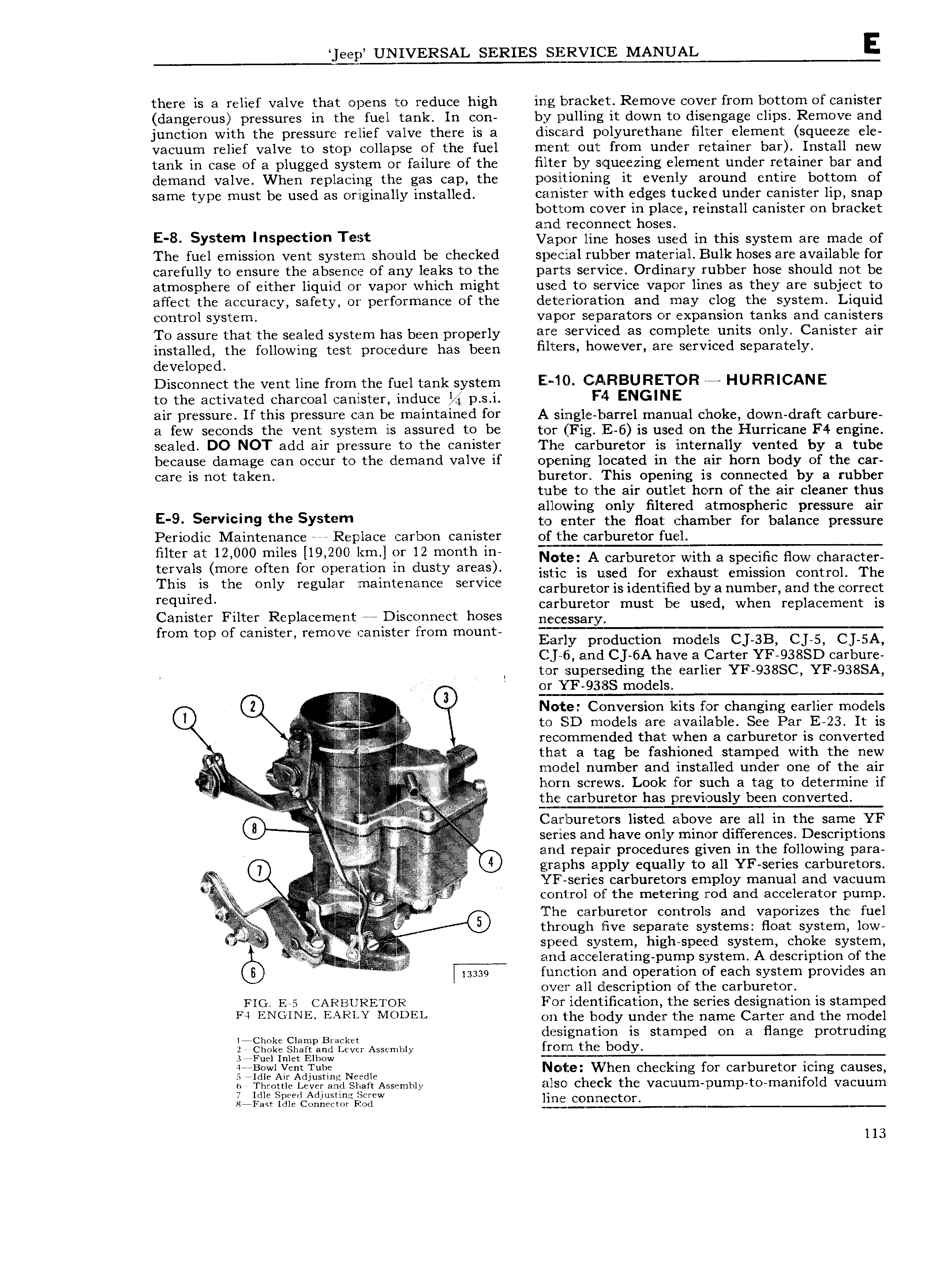
jeep UNIVERSAL SERIES SERVICE MANUAL E there is a relief valve that opens to reduce high ing bracket Remove cover from bottom of canister dangerous pressures in the fuel tank In con by pulling it down to disengage clips Remove and junction with the pressure relief valve there is a discard polyurethane filter element squeeze ele vacuum relief valve to stop collapse of the fuel ment out from under retainer bar Install new tank in case of a plugged system or failure of the filter by squeezing element under retainer bar and demand valve When replacing the gas cap the positioning it evenly around entire bottom of same type must be used as originally installed caznfister with edges tucked under canister lip snap bottom cover in place reinstall canister on bracket and reconnect hoses E 8 SY t m In P tI T rst Vapor line hoses used in this system are made of The fuel emission vent system should be checked special rubber material Bulk hoses are available for carefully to ensure the absence of any leaks to the parts service Ordinary rubber hose should not be atmosphere of either liquid or vapor which might used to service vapor lines as they are subject to affect the accuracy safety or performance of the deterioration and may clog the system Liquid control system vapor separators or expansion tanks and canisters Tg assuyg that the Scaled Systgrn has bqggn prgpgrly HIE 3 I VlC d HS COl Upl t L11 1ltS only C8I llSt tI Qlf installed the following test procedure has been m hvwevcr 3 76 i Vl d S P3Y t 1Y developed Disconnect the vent line from the fuel tank system E ll CARBURETOR E HURRICANE to the activated charcoal canister induce M p s i F4 ENGINE air pressure If this pressure can be maintained for A single barrel manual choke down draft carbure a few seconds the vent system is assured to be tor Fig E 6 is used on the Hurriwne F4 engine sealed DO NOT add air pressure to the canister The carburetor is internally vented by a tube because damage can occur to the d emand valve if opening located in the air horn body of the car care is not taken buretorz This opening is connected by a rubber tube to 1 he air outlet hc rn of the air cleaner thus allowing only filtered atmospheric pressure air E 9 S I V m9 the SY t m to enter the float chamber for balance pressure Periodic Maintenance Replace carbon canister of t he carburetor fuel mmf at 12 0OO miles l19 20OL Ein in iz month mi Note A carburetor with a specific fiow character t Y l mm Oftm Of lusty mea istie is ulsed for exhaust emission control The This is the Only reguldr mamtcmmcc Service carburetor is identified by a number and the correct required carburetor must be used when replacement is Canister Filter Replacement ee Disconnect hoses n CC ssary from top of canister remove canister from mount Eamy pmduction models CJSB CLS CLSAY Cj 6 and C 6A have a Carter YF 938SD carbure 1 tor superseding the earlier YF 938SC YF 938SA I gr Y 9f g S 0 9 Note Conversion kits for changing earlier models 0 4 i i i 1 to SD models are available See Par E 23 It is el i Y C0 11 1f1 Ild d that when a carburetor is converted iii Z that a tag be fashioned stamped with the new i iiiii iiAiiiiiiiiiii i i I U7iOCll l l ll11 Ub I 3I 1 Cl lI 1StElll d undef One 0f the air i i i i Screws I l f Such a mg t d t r i if 4 SEE Eggretor has p re Vi011SIy b I1 COHV I t Cl 0 iii i ii i iii Carlburetors listed above are all in the same YF series and have only minor differences Descriptions and repair procedures given in the following para 0 graphslapply equally to all YF series carburetors ivv X A j j V YF series carburetors employ manual and vacuum E g g control of the metering rod and accelerator pump V i The carburetor controls and vaporizes the fuel A through live separate systems fioat system low speed system high speed system choke system V gmt aceelerating piurrijn system A description of the i isssq function and operation of each syst em provides an over all description of the carburetor FIG E 5 CARBURETOR For identification the series designation is stamped F4 ENGINE EMEKLY MODEL on the body under the name Carter and the model licmkc Clamp Bracket designation is stamped on a flange protruding 2 clieke shan and Lever Asse mmy from the body 3 Fuel Inlet Elbow T j 7 T gijElg y2i rA d u f g Needle Ncnte W hen checking for carburetorlicing causes h Throttle Lever and Shaft Assembly ilSOl Ch Ck th V3C lJlI1H1 pI11 1 1 Z tO TIl3 I1lI Ol l VSCUUIII Llfllf i ii e 3 iL2iEi 1 i i L lim i t l 13