Ford Parts Wiki | GM Parts Wiki
Home | Search | Browse
Prev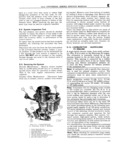

 Next
Next
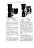
E FUEL SYSTEM 2 E 11 Float System E The float system Fig E 7 consists of a float float pin air horn gasket and the needle and seat i in A assembly These parts control the fuel level in the carburetor bowl a supply being maintained for all it systems under all operating conditions To prevent float vibration from affecting the fuel level the g Q 1 g E inlet or float valve is spring loaded Should the V4 needle and seat become worn they must be re r 3 zzg 9 placed with a matched set including the spring y j which is the only way they are supplied When g reinstalling the float be sure to install the float pin Q S V 0 with the stop shoulder on the side away from the bore of the carburetor E ini 1 0 E 12 Float Adjustment if Correct float level setting is required for accurate i 0 metering of fuel in both low and high speed jets t To set the float remove and invert the bowl cover Remove the bowl cover gasket Allow the weight 14 6l of the float to rest on the needle and spring Be sure there is no compression of the spring other Ffo E 6 VCARBURETOR than the weight of the float Adjust the level by El ENGINE LATE MODEL bending the float arm lip that contacts the needle j rgiuikelciiinpnrargk f e lg asj1II ot lunge2 ie1 not the arm to provide specifledeclearance be i ia i Q i Y 3 i 10 LSE NT2 Y mein She H 3t1 E1 j Th Seemed 1 a j i rB wlVe t h 1 Step Pi o t e oat is 64 mm on current mo es Ziibiiiiilriliittiiliyigt sgi Xgiilriridiliilgfiiig gcigw including Exhaust Emission Control and 7 l hrr ttl Lever 14 Fast Idle Connecting Rod nlm On Carly models ShOWn as A in E 8 iii I A E fi E i e a H H ee e g I l iit E l I f I i I 5 E ee 4 L L e A c EE5 Ef f i ci A r f 3 V I5 I 5 wl Q Z i A iiii E i A li iiii E i i i S It gm E S Elf Lf I E 0 i I ffifff I F W 3 if f 2i V I L tyj e t I Q f V a i t E eil it I 9 r 5 Em G l i I e V i E i i i Q 0 i V i i l t l t e ff i r e e jZ L f 0851 i L ELG E 8rFLOAT LEVEL GAUGLNG ii Q r j E 13 Low Speed System H i Fuel for idle and early part throttle operation is i l E i metered through the 1 w speed system The IOW A i I i speed system is illustrated in Fig E 9 Liquid fuel t A Qi enters the idle well through the metering rod jet me rr Low speed jet measures the amount of fuel for L idle and early part throttle operation Air by pass gm i E economizer and idle air bleed are carefully cali Qgfw as brated orifices which serve to break up the liquid FEW i E fuel and mix it with air as it moves through the I L i L passage to the idle port and idle adjustment screw in 2 l f fiiiiiii W 13362 E 14 Idle Mixture Adjustment FIG E 7 EEFLOAT SYSTEM Note The idle mixture adjustment procedure for rrF1 t d Leveremmhly the late model YF 4941S and YF 6115S Carter A 2 Needle Valve and Seat Assembly 3 Vent Carburetor equipped with the External Idle gigigzi BOW C Mixture Limiter Cap is the same as outlined below 114