Ford Parts Wiki | GM Parts Wiki
Home | Search | Browse
Prev
 Next
Next
1108375
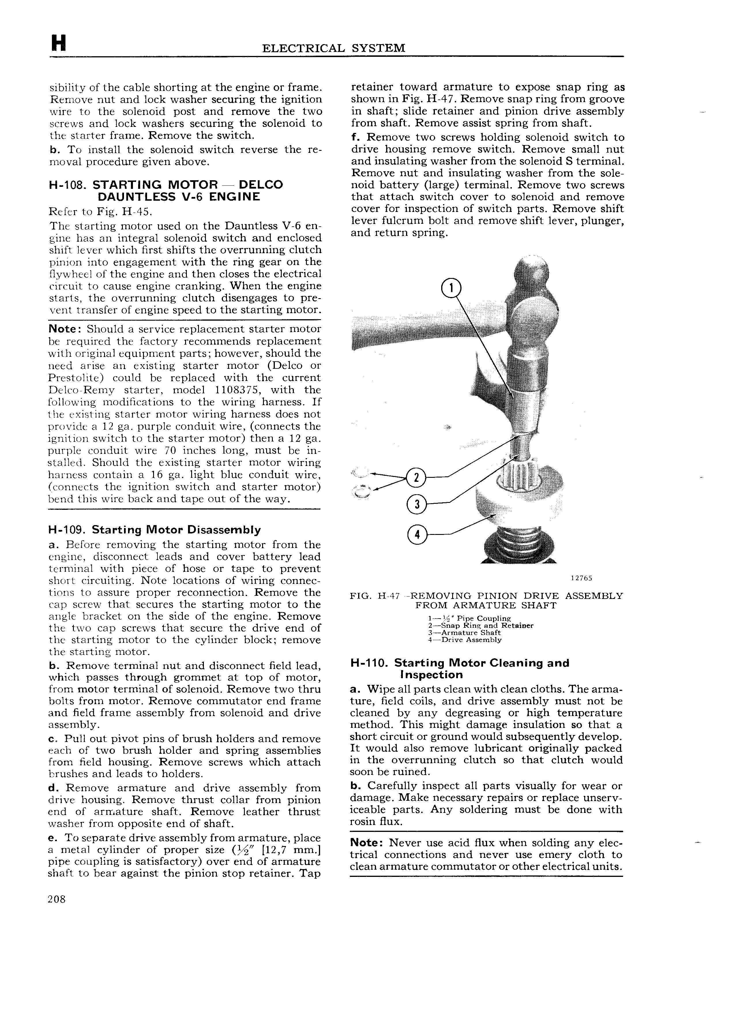
H ELECTRICAL SYSTEM sibility of the cable shorting at the engine or frame retainer toward armature to expose snap ring as Remove nut and lock washer securing the ignition shown in Fig H 47 Remove snap ring from groove wire to the solenoid post and remove the two in shaft slide retainer and pinion drive assembly screws and lock washers securing the solenoid to from shaft Remove assist spring from shaft tho i Yl f fY3m Rornovo tl switch f Remove two screws holding solenoid switch to b To install the solenoid switch reverse the re drive housing remove switch Remove small nut moval procedure given above and insulating washer from the solenoid S terminal Remove nut and insulating washer from the sole H 108 STARTING MOTOR 4 DELCO noid battery large terminal Remove two screws DAUNTLESS V 6 ENGINE that attach switch cover to solenoid and remove Rerer tc Fig H 45 cover for inspection of switch parts Remove shift Ths Starting mmm used On the Dalmtlcss V 6 CH lever fulcrum bolt and remove shift lever plunger gine has an integral solenoid switch and enclosed and return Sprmg shift lever which first shifts the overrunning clutch r pinion into engagement with the ring gear on the flywheel of the engine and then closes the electrical l circuit to cause engine cranking When the engine g g ilv starts the overrunning clutch disengages to pre i vent transfer of engine speed to the starting motor t s or N io Snoulri a sorvioo roolaoornonr siarrrr motor r i be required the rrnctcry recommends replacement r r r r i l with original equipment parts however should the need arise an existing starter motor Delco or i Prestolite could be replaced with the current 2 i j j A Delco Remy starter model 1108375 with the following modifications to the wiring harness If the existing starter motor wiring harness does not provide a 12 ga purple conduit wire connects the in V ignition switch to the starter motor then a 12 ga purple conduit wire 70 inches long must be in stalled Should the existing starter motor wiring r l harness contain a 16 ga light blue conduit wire lw 6 i i it connects the ignition switch and starter motor g e Fi bend this wire back and tape out of the way L H 109 Starting Motor Disassembly a Before removing the starting motor from the engine disconnect leads and cover battery lead tt 3 terminal with piece of hose or tape to prevent short circuiting Note locations of wiring connec 12705 tlOIlS to HSSUYC pI Op I I CO1 11 l CtlOH RCIHOVC th FIG H 47 REMOVING PINION DRIVE ASSEMBLY cap screw that secures the starting motor to the FROM ARMATURE SHAFT angle bracket on the side of the engine Remove 1 LQ PipeC0upIing the two cap screws that secure the drive end of iQ a 1fjfS f tR l the starting motor to the cylinder block remove 44Drivs Assembly the starting motor b Remove terminal nut and disconnect field lead l l 110 Stal tl 9 M t Claa l 9 and which passes through grommet at top of motor lnslaactlon from motor terminal of solenoid Remove two thru a Wipe all parts clean with clean cloths The arma bolts from motor Remove commutator end frame ture field coils and drive assembly must not be and field frame assembly from solenoid and drive cleaned by any degreasing or high temperature assembly method This might damage insulation so that a o Poli out pivot pins or brush holders and remove short oirouit or ground would subsequently dovolop each of two omit holder and spring assembiies It would also rornovo lubricant originally packed from field housing Remove screws which attach in rho 0V Yluul llag oluroh SO that clutch would brushes and leads to holders SOOU bo l ulu d d Remove armature and drive assembly from b Carofully insooot all Darla visually for woar Ol drive housing Remove thrust collar from pinion damage Mako u S al Y Y palls OY roplaoo u l V end of armature Short Remove ieathet thrust icoablo parts Any soldorins must bo dono with washer from opposite end of shaft mam Hux e To separate drive assembly from armature place Note Never use acid Hux when Solding any r c 3 metal ll l f gf rroarr SIZE l12 7 mm l trical connections and never use emery cloth to p p 3 l l g is Satisfactory Over and of armature clean armature commutator or other electrical units shaft to bear against the pinion stop retainer Tap 208