Ford Parts Wiki | GM Parts Wiki
Home | Search | Browse
Prev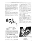
 Next
Next
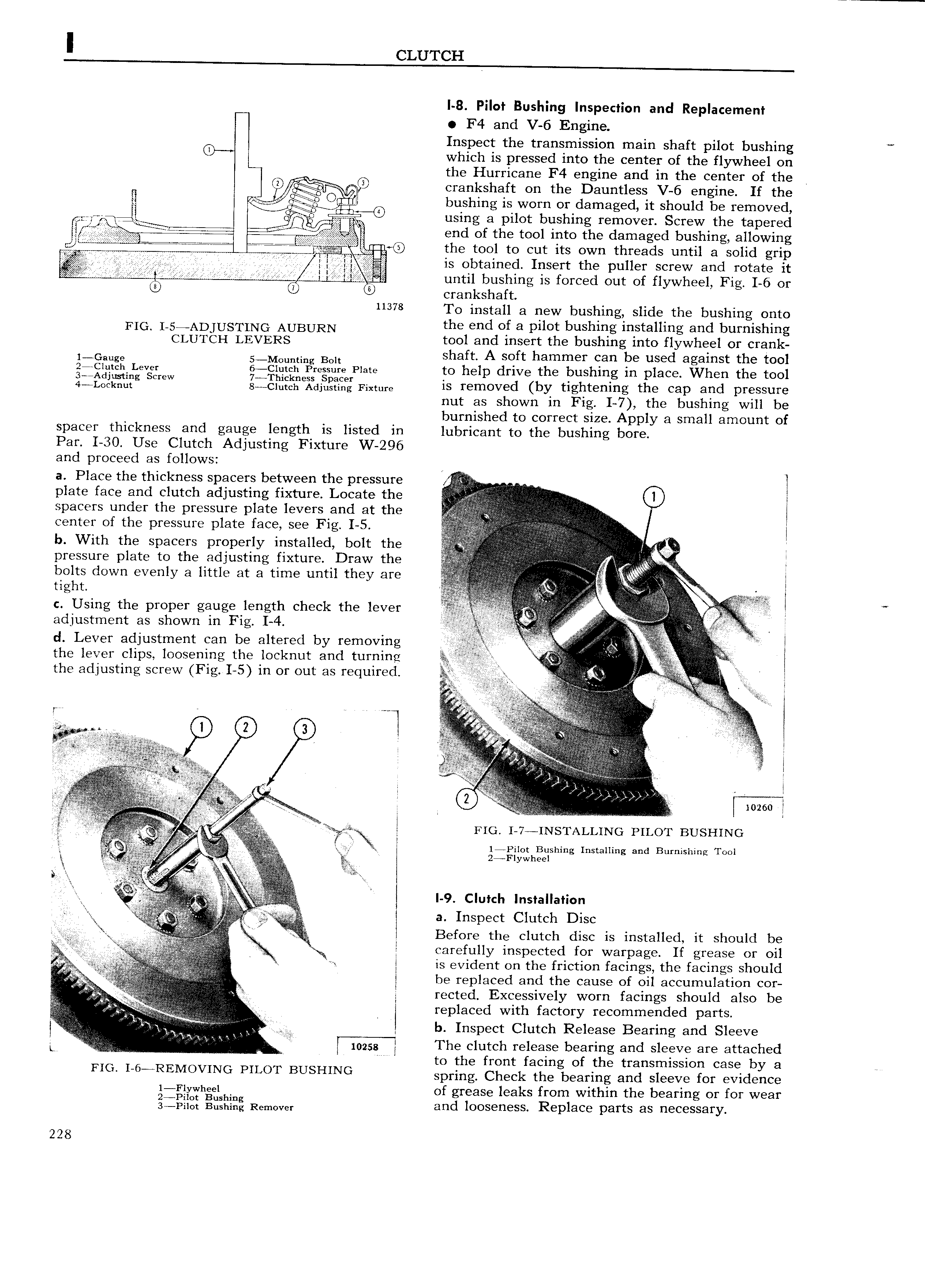
I CLUTCH I 8 Pilot Bushing Inspection and Replacement F4 and V 6 Engine Inspect the transmission main shaft pilot bushing 0 which is pressed into the center of the flywheel on wu the Hurricane F4 engine and in the center of the C 1 crankshaft on the Dauntless V 6 engine If the El e n O l bushing is worn or damaged it should be removed I kiG E using a pilot bushing remover Screw the tapered l end of the tool into the damaged bushing allowing mvp p p p p 7 V W ga the tool to cut its own threads until a solid grip 2 p s Qg i p j g is obtained Insert the puller screw and rotate it rr M 2 E until bushing is forced out of fl Wheel Fi I 6 or Y g 0 6 crankshaft 11378 To install a new bushing slide the bushing onto FIG I 5 ADJUSTING AUBURN the end of a pilot bushing installing and burnishing CLUTCH LEVERS tool and insert the bushing into flywheel or crank 1 G8uge S MOuming Bolt shaft A soft hammer can be used against the tool ge ijq h L v r gs g iqiih Pregsure Plate to help drive the bushing in place When the tool 4 LO 5 tQ g New 8jCPQ e dju i Q Fixtme is removed by tightening the cap and pressure nut as shown 1n Fig I 7 the bushing will be burnished to correct size Apply a small amount of spacer thickness and gauge length is listed in lubricant to the bushing bore Par I 30 Use Clutch Adjusting Fixture W 296 and proceed as follows a Place the thickness spacers between the pressure l plate face and clutch adjusting fixture Locate the R Z IZ E spacers under the pressure plate levers and at the t center of the pressure plate face see Fig I 5 if tj g i fj n g 5 g A b With the spacers properly installed bolt the fi l iQf i p pressure plate to the adjusting fixture Draw the ij r Q 1 V t r s r i bolts down evenly a lrttle at a time until they are szj 2 V t V U e g U tight t t t C l 5 5 Q t 1 c Using the proper gauge length check the lever e M Vj r l adjustment as shown in Fig I 4 t f r i t r js i d Lever adjustment can be altered by removing V 5V r C Q s C r the lever clips loosening the locknut and turning U 1 the adjusting screw Fig I 5 in or out as required irp i gA if i I 0 A I grf l A x Q Z l if 1 I I j i n l r j A jjj V i 3 I Al 1 ce j awe Y f e i 0 Ni r Y 10260 gy r 1 V j sl at Fro r 7 INSTALLING PILOT BUSHING g I Rv t j 1 Pilot Bushing Installing and Burnishing Tool it t tg 2rF yWhe t isf l i C i l l 9 Clutch Installation r t if i E gx e 1 a Inspect Clutch Disc f i LZ E g t 3 Before the clutch disc is installed it should be F j j carefully inspected for warpage If grease or oil is evident on the friction facings the facings should A l be replaced and the cause of oil accumulation cor s t t vi e t i reeted Excessively worn facings should also be I replaced with factor recommended arts pt j t t r 2 it y P n 7tx t I C j b Inspect Clutch Release Bearing and Sleeve A v x 1 xi X eg t 7 I h 1 d 1 h d L U I mzgg Y T e c utch release bearing an s eeve are attac e to the front facing of the transmission case by a FIG 1 6 REMOV1NG PILOT BUSHING spring Check the bearing and sleeve for evidence gl wh el h of grease leaks from within the bearing or for wear 3iP g Bxihlgg Remove and looseness Replace parts as necessary 228