Ford Parts Wiki | GM Parts Wiki
Home | Search | Browse
Prev
 Next
Next
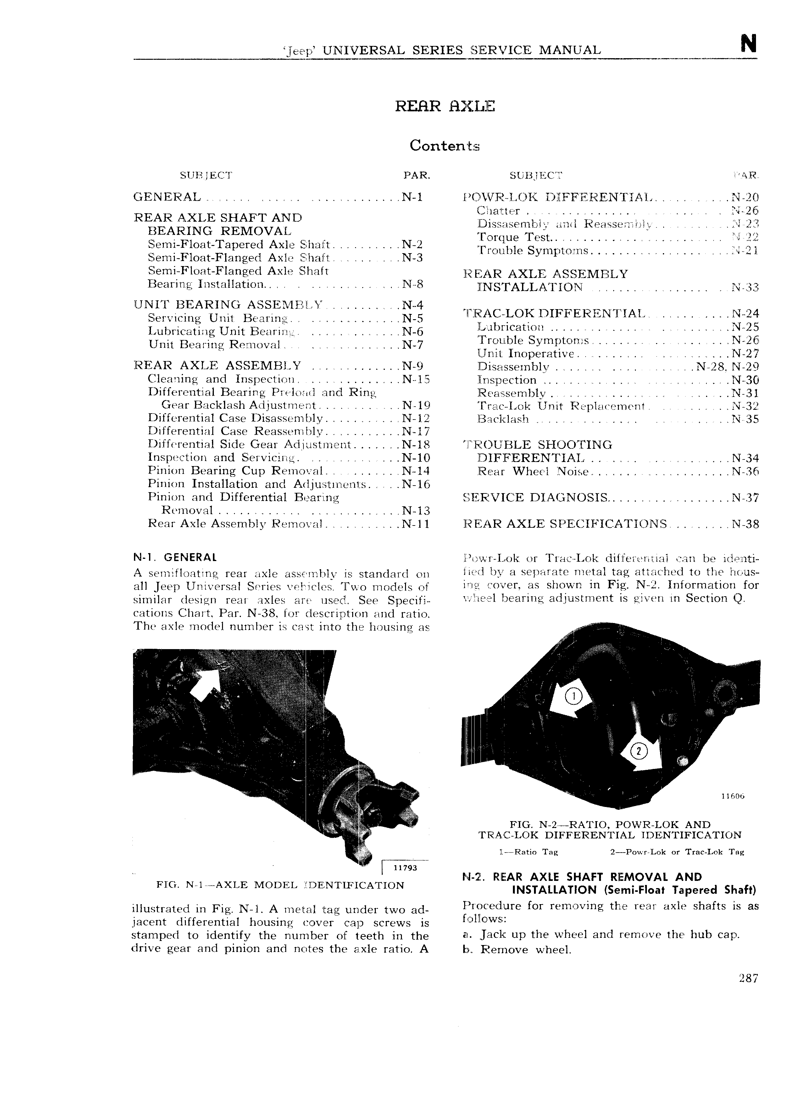
Ve ep UNIVERSAL SERIES E S lEP I ICE MPEUAL w N REHR H i l 1llEZ Contents SUB EC l PAR SUI3 IiC 1 WAR GENERAL 1 L N 1 l VVVR l C K DIIFFVERENTIAL N 2 I C liatte r l 2G llDi ss 1senibl ami Reasserzznlg A 1 22 I e T s f 122 Semi Float Tapered Axle Eiiliziilt N 2 TQ 3 i Sgiqpmms KQ Siemi Float Flanged Axle EE liall i N 3 V V I 4 V ii Semij loz1t Flang ed Axle filhalt g g pj AR AXLE ASSfj BLVY Bearing Installationl l N 8 N S FALLA IOl 4 Nogg l NIT BEARINC A El IliE l J q l Vi mg rUm1 B 3 mO gf l lEEEAC LOK DIFFERENTIAL N 24 Lubricating Unit Bearing L N 6 gll lI r l8t U C UV EBY Rm zll V V N 7 rQUl G y is I mt td mg P mw 1 Unit Inoperative 1 Y N 27 REAR AXLE ASSEMBLY 4 N 9 lDisasseinhly 1 N 28 N 29 Cleaning and Inspection N l5 llnspection l N 30 I if ferential Bearing Pieloail and Ring lRea s seinbly l 1 N 31 Gear Backlash Adjustment N 19 l ra Lol Unit Replavemenl N 32 Differential Case Disassenilily l N l 2 IE3acl lash 4 r l N 35 Differential Case Reassemhly l N l7 Differential Side Gear Cl Ii lSKlTl lTIl N 18 l IiiE UVBLE SHOOTING Inspection and Servicing i N IO lDIFFERENTIAI 4 N 34 Pinion Bearing Cup Reinoisal NQI4 Rear Wheel Noise N 36 Pinion Installation and A l ju stinen1 s l N 16 Pinion and Differential Bearing lE l FiiVI CE DIAGNOSIS l i N 37 Removal u N 13 Rear Axle Assembly Removal l i N ll ll EAR AXLE SPECIFICATIONS N 38 N GENERAL l wr I 1c I or l rae I ol dillferemial can be i lenti A semifloating rear axle ass 1nI ly is standard on lli VI by ki l ll iY llliflgl leg ll hCd IU lll l U all jeep Universal Series veliricles Two models of l 7 i V0 V V is SIWWH m N UfOYm UO for similar design rear axles are used See Specifi iI l b mU 3dJ IStm mt ls lV In Section cations Chart Par N 38 for description and ratio The GXIG WTIOCIGI Uutnber is Cast into the housing gg i I l l i V Q I I I 1 I V j N V N V I a j f i v r T V V X L 4 1 Ai I Q A r i H V W I V k i 11600 I FIG N 2 RATIO POVVR LOK AND VI RlA C LOK DIFFERENTIAL IDENTIFICATION TZ lL Ratin Tag 2 Powi Lok or Ti ac Lok Tag T 11793 I N r I I if RlEEAR AXLE SHAFT RIEMOVAL AND FIG N 1 AXLE MODEL lDENT FI A ON INSTALLATION Semi Float Taipered Shaft mugtmtgd in Fig N 1 A mgm mg under two 3d lFV roCed iure for removing the rear axle shafts is as jacent differential housing cover cap screws is i O IlO vvSi stamped to identify the number of teeth in the El I3 I i UD Th Wh v 1 d V m V UW hub 8P drive gear and pinion and notes the axle ratioi A I Remove wheel 287