Ford Parts Wiki | GM Parts Wiki
Home | Search | Browse
Prev
 Next
Next
77777777
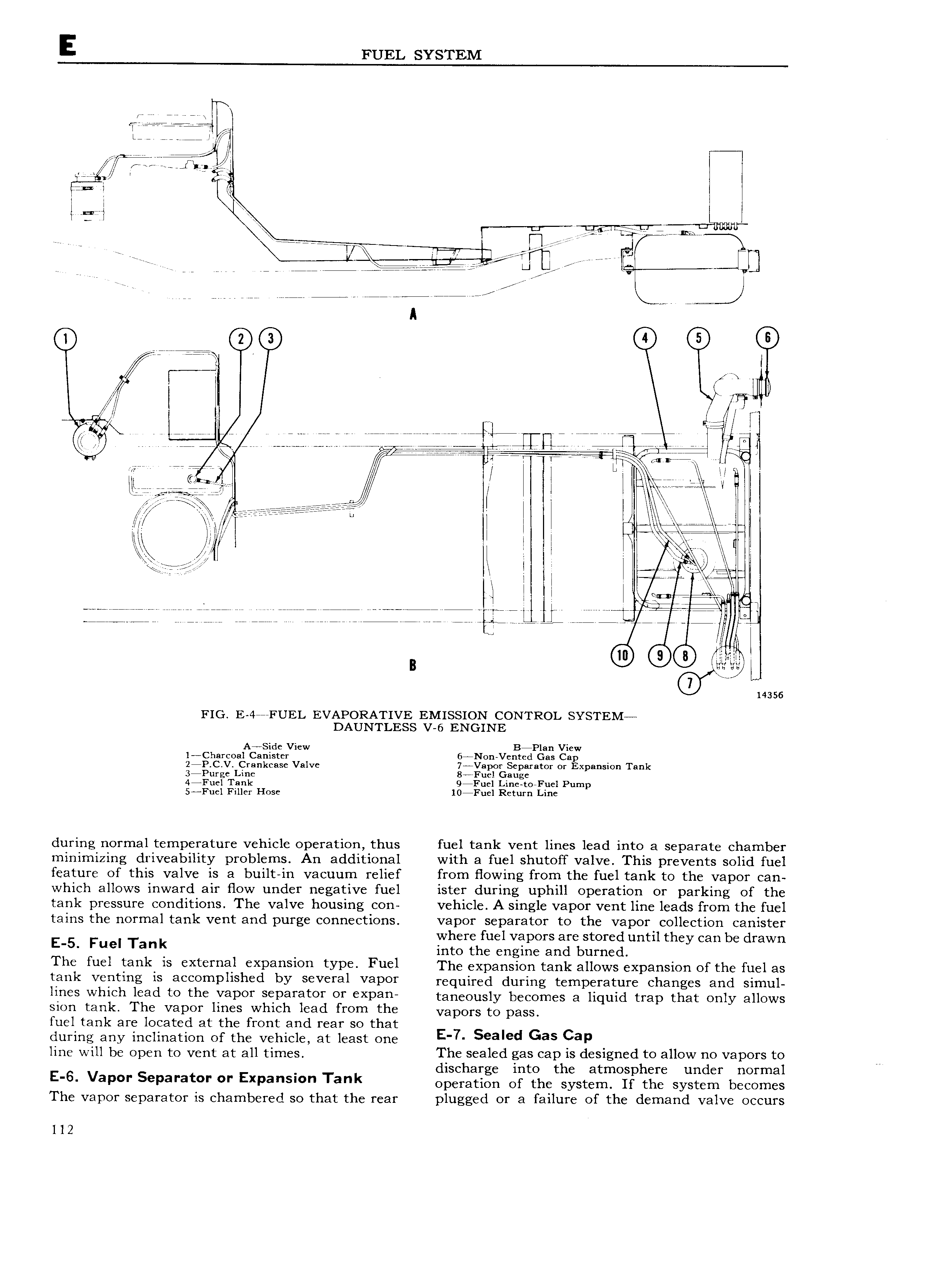
E FUEL SYSTEM 7 1 2 i1Sje iQS I Ii I I I I I I peri S Sglmm KK I 7 e n7WrTyf J r V aatI Ij rr r J rr 7 7 f I i iW S I S ieS 5 CZ IJ S 7 7 VQ A e TYWWYEEQ I I r S S IIlI I I SS IS I 5 V V e e e e e ee W rr 7 Wi rni L V 7 77777777 Nr 7 Y V L 77 I e S e e e Veneer i1 iS V Q TSSSSSQ 7 0 l i eee ei S ee L s at eee Q IE if T WV IIIYVT Ziff BSSTSS I I I I I E I I I I I I 4 Ir SS ii r G I I I QI III II I I rei iS n III I I le II I I I SS Sl I I ii F7 S I I TSS S L il I I V I l 7 I I p gg IQ W or jjii jg S SSIS ii SIIS G SSSS ijiii TSQIS I SIS S S S S j il IJ I I I B Q 0 0 CD mss FIG E 4 FUEL EVAPORATIVE EMISSION CONTROL SYSTEM DAUNTLESS v 6 ENGINE l Charcoaf ig e1Yi w 6ANon Ver edPglars gf 2 P C V Crankcase Valve 7 Vapor Separator or Expansion Tank 3 Purge Line 8 Fuel Gauge 44Fuel Tank 9 Fuel Line to Fuel Pump 5 Fuel Filler Hose 10 Fuel Return Line during normal temperature vehicle operation thus fuel tank vent lines lead into a separate chamber minimizing driveability problems An additional with a fuel shutoff valve This prevents solid fuel feature of this valve is a built in vacuum relief from flowing from the fuel tank to the vapor can which allows inward air fiow under negative fuel ister during uphill operation or parking of the tank pressure conditions The valve housing con vehicle A single vapor vent line leads from the fuel tains the normal tank vent and purge connections vapor separator to the vapor collection canister where fuel vapors are stored until they can be drawn E 5 Fuel Ta into the engine and burned T he fuel tenk is external expnnsipn type Fuel The expansion tank allows expansion er the fuel as tank venting ls 3 OmPll h d bY V l l V3POY required during temperature changes and simul lll l Whl h lead te the VQPOY SQDQYQWY Ol XD3 taneously becomes a liquid trap that only allows sion tank The vapor lines which lead from the vapors to paSS fuel tank are located at the front and rear so that during any inclination of the vehicle at least one E Sealed Gas Cap line will be open to vent at all times The sealed gas cap is designed to allow no vapors to discharge into the atmosphere under normal N E 6 VaP S pa at ExPa s Tank operation of the system If the system becomes The vapor separator is chambered so that the rear plugged or a failure of the demand valve occurs l 12