Ford Parts Wiki | GM Parts Wiki
Home | Search | Browse
Prev
 Next
Next
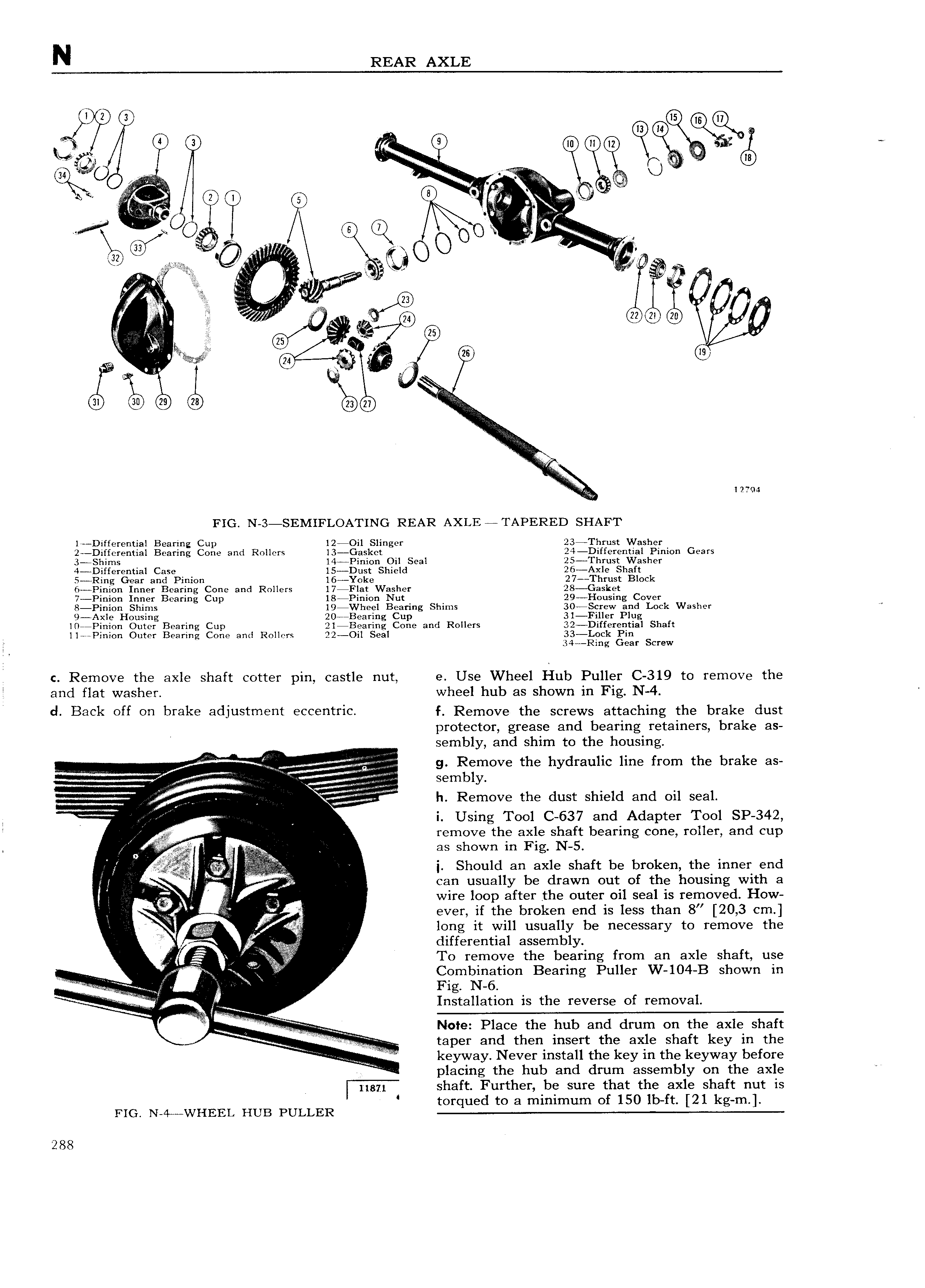
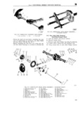
N REAR AXLE 3 e on kk w 3 1 A A z G Q Q V 5 I Qt r 9 34 U i in will V 5 0 I rg I Q r iU 5 I A V if Q i 5 I t Q c 2 5 U I I gsi l F dl lgiqf I I s 3 an Q 7 l27 4 FIG N 3 SEMIFLOATING REAR AXLE TAPERED SHAFT lr Differential Bearing Cup l2 Oi1 Slinger 23 Thrust Washer 2 Diffcrential Bearing Cone and Rollers l3 Gasket 24 Differential Pinion Gears 3 Shims l4 Pinion Oil Seal 25 Thrust Washer 4 Differential Case l5 Dust Shield 26 Axle Shaft 5 Ring Gear and Pinion l6 Yoke 27 Thrust Block 6 Pinion Inner Bearing Cone and Rollers 17iFlat Washer 28 Gasket 7 Pinion Inner Bearing Cup 18 Pinion Nut 29 Housing Cover 8 Pinion Shims 19 Wheel Bearing Shims 30 Screw and Lock Washer 9 Axle Housing 20 Bearing Cup 31 Filler Plug l0 Pinion Outer Bearing Cup 2l Bearing Cone and Rollers 32 Differential Shaft ll Pinion Outer Bearing Cone and Rollers 22 Oil Seal 33 L0ck Pin 34 Ring Gear Screw i c Remove the axle shaft cotter pin castle nut e Use Wheel Hub Puller C 319 to remove the and flat washer wheel hub as shown in Fig N 4 d Back off on brake adjustment eccentric f Remove the screws attaching the brake dust A protector grease and bearing retainers brake as sembly and shim to the housing j Q f V H T y g g Remove the hydraulic line from the brake as V sembly h Remove the dust shield and oil seal g nm i Q i Using Tool C 637 and Adapter Tool SP 342 I V A remove the axle shaft bearing cone roller and cup 2 as shown in Fig N 5 i 1 Should an axle shaft be broken the inner end g A i can usually be drawn out of the housing with a wire loop after the outer oil seal is removed How f ever if the broken end is less than 8 20 3 cm long it will usually be necessary to remove the differential assembly V r To remove the bearing from an axle shaft use Combination Bearing Puller W 104 B shown in if F X Fig N 6 Installation is the reverse of removal f r e e M Note Place the hub and drum on the axle shaft taper and then insert the axle shaft key in the i W r l keyway Never install the key in the keyway before placing the hub and drum assembly on the axle 1 5 shaft Further be sure that the axle shaft nut is torqued to a minimum of 150 lb ft 21 kg m FIG N 4 WHEEL HUB PULLER 288